9 Electricity

How can charges move?

Contents

  • Electric Potential and Circuits
  • Electric Currents and Circuits
  • Ohm’s Law
  • Electric Power and Energy Conversion

Key Points from Electromagnetism

Charge Unit: Coulomb (C)

  • Electric Fields

    • Region where charges experience force
    • Field strength:
    • Charges in fields have
    Movement +q -q
    Along Field
    Against Field
  • Electric Potential Energy

    • Energy stored in charge within fields
    • Depends on charge separation
    • Measured in Joules (J)
  • Electric Potential (Voltage)

    • Energy stored in fields themselves
    • Energy per unit charge (V)

The “Life Force”

Luigi Galvani (1737–1798)

  • 1791: Static electricity causes a frog leg to twitch.
  • Twitching also induced by metals.
  • Metals thought to conduct the animal's "life force".

Skeptical Interrogation

Alessandro Volta (1745–1827)

Galvani’s "life force" claim questioned.

  • Experiments showed metals were the source of electricity, conducted by frog tissue.
  • Debunked idea that electricity is only in living things.

Volta Pile

  • The first battery, invented by Volta.
  • Each layer produced about 0.7 volts of electricity.
  • Used alternating discs of zinc and copper separated by cardboard soaked in saltwater.
  • Napoleon was so impressed he made Volta a count in 1801.

Electric Batteries

  • Batteries convert chemical energy into electrical energy.
  • Provide a constant voltage (EMF) to a circuit.
  • Parts: Anode (−), Cathode (+), Electrolyte.
  • Key Point: Batteries "push" electrons through the circuit.

Current Diagram Symbols

alt text

  • The longer line indicates the positive terminal; shorter indicates negative
  • Open switches prevent electrical energy flow; closed switches permit it

  • Capacitors work as batteries except release charge instantly and must be charged again
  • Fuses are designed as deliberate fault points to prevent permanent system damage
  • Resistors can be anything that consume energy; almost always loss as heat

Circuit Diagram Norms

  • Use standardized symbols (battery, resistor, capacitor etc.)
  • Draw straight lines with 90° angles for wires
  • Avoid wire crossings where possible; use dots for connections
  • Label components with values (V, , etc.)
  • Show conventional current flow (+ to -)
  • Keep diagrams simple and uncluttered
  • Represent resistors and consumers with appropriate symbols:
    • Resistors: zigzag lines for pure resistance
    • Consumers (lamps, motors): specific symbols showing energy conversion
zoom

Electric Current Analogy

  • Charge flow in a conductor is like water in a pipe.
  • Charge flows from high to low potential
  • Charge spreads to share all paths
  • Flow depends on paths available

Electricity and Magnetism

André-Marie Ampère (1775-1836)

  • Discovered relationship between electricity and magnetism
  • Ampere (A): Unit of electric current

Electric Current

left

  • Electric current (I) is the flow of electric charge.
  • Not the flow of electrons!
  • Measured in amperes (A).

Visualizing the flow of charge

  • Conventional current: Direction positive charges would flow (from + to −).
    • Charge is said to flow from the positive to the negative terminal through the circuit
    • Electrons would be visualized moving from the negative toward the positive terminal against the current
    • Electrons move very slowly (drift velocity ~1mm/s)

Misconceptions about Electric Current

  • Energy transfer in circuits is near light speed (despite drift velocity)
  • Like dominoes: push one end, other end falls instantly
  • Electrons bump into each other, transferring energy
  • Like pushing water in a full pipe: instant flow at other end

Ohm’s Law

Georg Simon Ohm (1789-1854)

  • Discovered the relationship between voltage, current, and resistance.
  • Ohm's Law: The current through a conductor is directly proportional to the voltage across it, provided temperature remains constant.

  • The Ohm (Greek Omega, ) is the unit of resistance:

Simple Ohm's Law Units Example

Example: If V and , then A.

(Complex) Cancellation to SI Base Units

  • For resistance ():

  • Therefore,

Resistivity

  • Resistance depends on material, length, and area.
  • The resistivity of a section of circuit is given as:

    Where

    • = resistivity (·m)
    • = length (m)
    • = cross-sectional area (m²)

Practical Resistivity

Material Resistivity (·m)
Wood (dry)
Rubber
Glass
Human Skin (dry)
Salt Water
Iron
Aluminum
Copper

Table 1 Resistivity of common materials.

  • One way to think of resistivity is how much energy will be lost as heat as the charge flows through it.
  • a) Copper conducts the electricity.
  • b) Wood catches fire.
  • c) Biological tissues experience burns

Resistance and Resistors

  • Resistance: How much a material opposes current flow.
  • Resistors: Components designed to introduce resistance.
    - Application: convert electrical into thermal energy

padding: 2px

Ohm’s Law in Circuits

center width: 200px

  • When current flows through a resistor, a voltage drop is experienced.
  • Force on the charge is no longer balanced because one path is energetically "easier" to follow
  • Visualize resistance as a narrow pipe or thumb over a hose.

The voltage drop can be calculated using Ohm's Law:

EMF and Terminal Voltage

  • EMF (Electromotive Force): The ideal voltage a battery provides.
  • Terminal Voltage: Actual voltage across battery terminals (can be less than EMF due to internal resistance).

Where

  • = internal resistance

Series vs Parallel Circuits

- All resistors are aligned in a single circuit
- The same current exists throughout
- Voltage divides across components
- Higher total resistance
- Multiple paths for current
- Current divides between paths
- The same voltage across branches
- Lower total resistance

Series vs Parallel Applications

Series Circuits

  • Christmas lights (old style)
  • Battery-powered devices
  • Voltage dividers
  • If one breaks, all stop

Parallel Circuits

  • Home wiring
  • Modern Christmas lights
  • Multiple device outlets
  • If one breaks, others work

Resistors in Series

Resistance in Series Circuits
Total resistance:

Resistors in Parallel

  • Solving resistors in parallel requires taking the reciprocal of the sum of the reciprocals.

Resistance in Parallel Circuits
Total resistance:

  • This is because the current can take multiple paths, and the total current is the sum of the currents through each path.
  • When solving, remember to take the reciprocal of the final answer to find the equivalent resistance.
    • Adding the fractions requires a common denominator.

Electrical Power

  • Power (P) is the rate at which energy is transferred
  • In circuits, power is energy per unit time
  • Measured in watts (W):

Power and Work

Energy Connection

  • Work done by electric force:
    - Work from charge and voltage:
    - Power from work over time:
    - Current as charge over time:
    - Substituting current:

Therefore:

Converting Units to Energy and Power

  • Power (watts) is a measure of energy per second
  • 1 watt = 1 joule per second

  • A 100W device uses 100 joules of energy each second

  • Total energy = power × time (joules = watts × seconds)

Three equivalent formulae for electrical power:

Common Electrical Power Requirements

Device Voltage (V) Power (W) Notes
iPhone Charger 5 20 USB-C Power Delivery
MacBook Pro 20 140 Via USB-C/MagSafe
Refrigerator 120 150 Energy-efficient model
Gaming PC 120 750 Under full load
Microwave 120 1,000 Standard household unit
Electric Kettle 120 1,500 Boils water in ~4 minutes
Air Conditioner 240 3,500 Central home unit
Tesla Model 3 400 250,000 Peak power during acceleration
Boeing 787 115 1,000,000 Main electrical system

Problem 1: Series Circuit Analysis

A circuit contains three resistors in series: , , and . If connected to a 12 V battery:

a) What is the total resistance?
b) What is the current through each resistor?
c) What is the voltage drop across each resistor?

  • a) Approach: For resistors in series, add individual resistances.

  • b) Approach: With total resistance known, apply Ohm's law to find current.

  • c) Approach: In series circuits, use Ohm's law to find voltage drop across each resistor.


Problem 2: Power Consumption

A circuit has a 9 V battery connected to a 3 resistor:

a) What is the current in the circuit?
b) What is the power dissipated by the resistor?
c) How much energy is converted to heat in 5 minutes?

Solution:

  • a) Approach: Apply Ohm's law directly to find current.

  • b) Approach: Use power formula with known current and resistance.

  • c) Approach: Convert power to energy by multiplying by time in seconds.

Problem 3: Parallel Circuit

Two resistors are connected in parallel: and . If the voltage across them is 12 V:

a) What is the equivalent resistance?
b) What is the total current from the battery?
c) What is the current through each resistor?

Solution:
- a) Approach: For parallel circuits, add the reciprocals of individual resistances, then take the reciprocal of that sum.
;

  • b) Approach: Once you have the equivalent resistance, apply Ohm's law with the total voltage to find total current.

  • c) Approach: In parallel circuits, each component receives the full voltage. Apply Ohm's law to each resistor separately.
    ;

Formula Summary

Category Concept Formula Units/Notes
Fundamentals Current A (Amperes)
Electric Potential V (Volts)
Ohm's Law Basic Form V = A × Ω
Resistance Form Ω (Ohms)
Power Voltage-Current W (Watts)
Current-Resistance W = A² × Ω
Voltage-Resistance W = V² ÷ Ω
Circuit Analysis Series Resistance Total increases
Parallel Resistance Total decreases

![bg right contain](../assets/images/9_electricity/ampere-unit.svg) The ampere was defined relative to the force between parallel current-carrying conductors: - Two conductors 1m apart - Each carrying 1 ampere - Experience a force of 2×10⁻⁷ N per meter ---
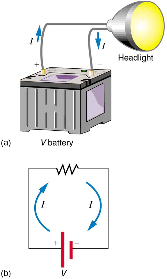
# Kirchhoff's Laws <div class='flexbox'> <div> 1. **Kirchhoff's Current Law (KCL)**: The total current entering a junction equals the total current leaving it. - $$\sum I_{in} = \sum I_{out}$$ - * Conservation of charge: charge cannot be created or destroyed. 2. **Kirchhoff's Voltage Law (KVL)**: The sum of the potential differences (voltage) around any closed loop in a circuit is zero. - $$\sum V = 0$$ - * Conservation of energy: energy supplied equals energy consumed. - *Voltage drop across resistors equals voltage rise across sources (batteries).** 3.

![Simple circuit diagram](../assets/images/9_electricity/simple-circuit-projector.jpg)

<div class='important-info'>

<div class='important-info'>

<div class='important-info'>

![width:500px drop-shadow](../assets/images/9_electricity/step-up-transformer-real.jpg)

|Unit|Unit Relationships| |-|-| | Resistance (unit) | $1~\Omega = \frac{1~V}{1~A}$ | 1 Ohm = 1 Volt / 1 Ampere | | Power (unit) | $1~W = 1~V \cdot 1~A$ | 1 Watt = 1 Volt × 1 Ampere | | Power (unit) | $1~W = 1~\frac{J}{s}$ | 1 Watt = 1 Joule per second |